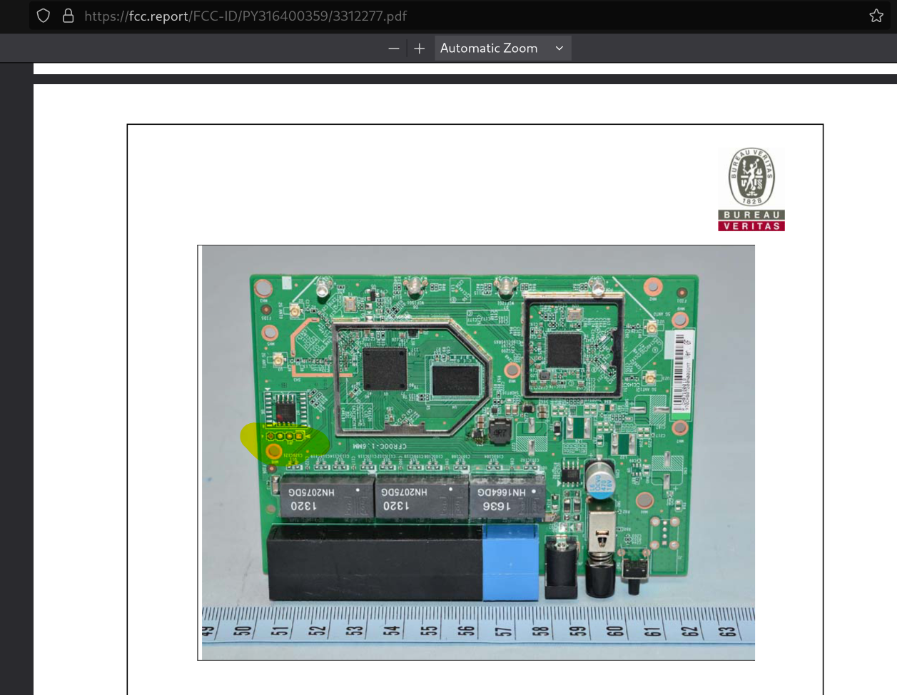
I decided to check out my local Goodwill for old routers that I might be able to get a shell on. By looking at the device’s FCC ID, I was able to review the internal photos and identify exposed UART pins.
https://fcc.report/FCC-ID/PY316400359/3312277.pdf
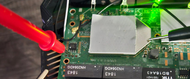
With the device set up in the lab, the next step is to enumerate each pin and align it with the corresponding pin on the adapter.
1. Find the Ground Pin
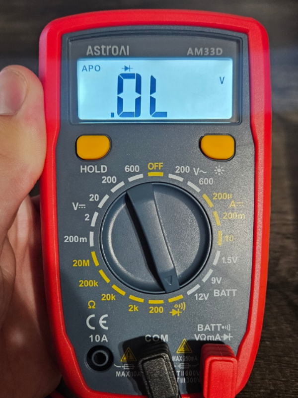
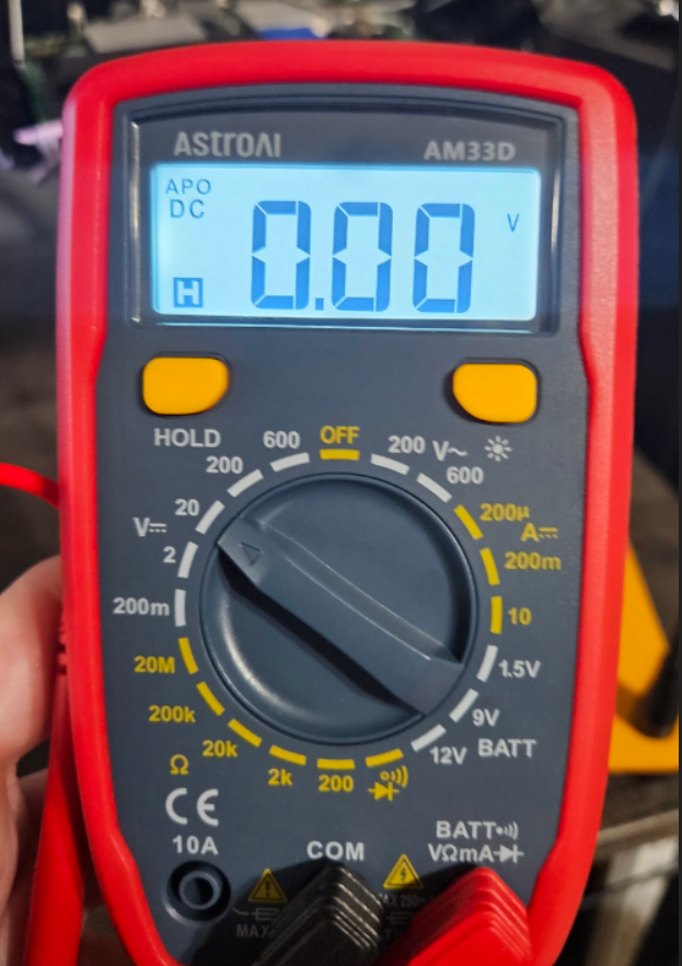
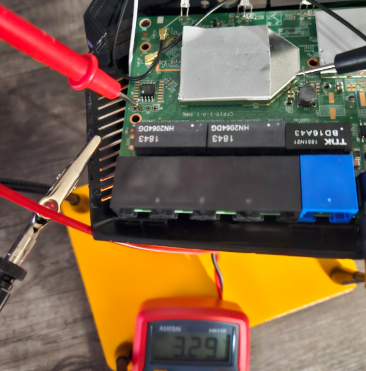
Power off the device and use your multimeter to check each pin for ground. Make sure your meter is set to the same configuration as mine.
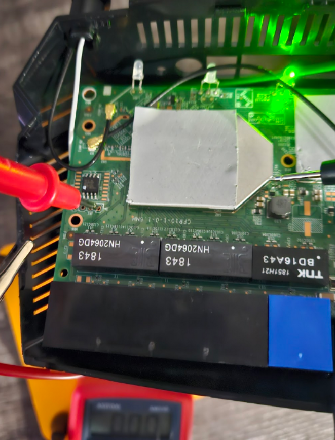
On my device, the ground pin was the furthest left from the power button. If you’ve set everything correctly, you should hear a beep when testing. Ensure the black probe is connected to ground.
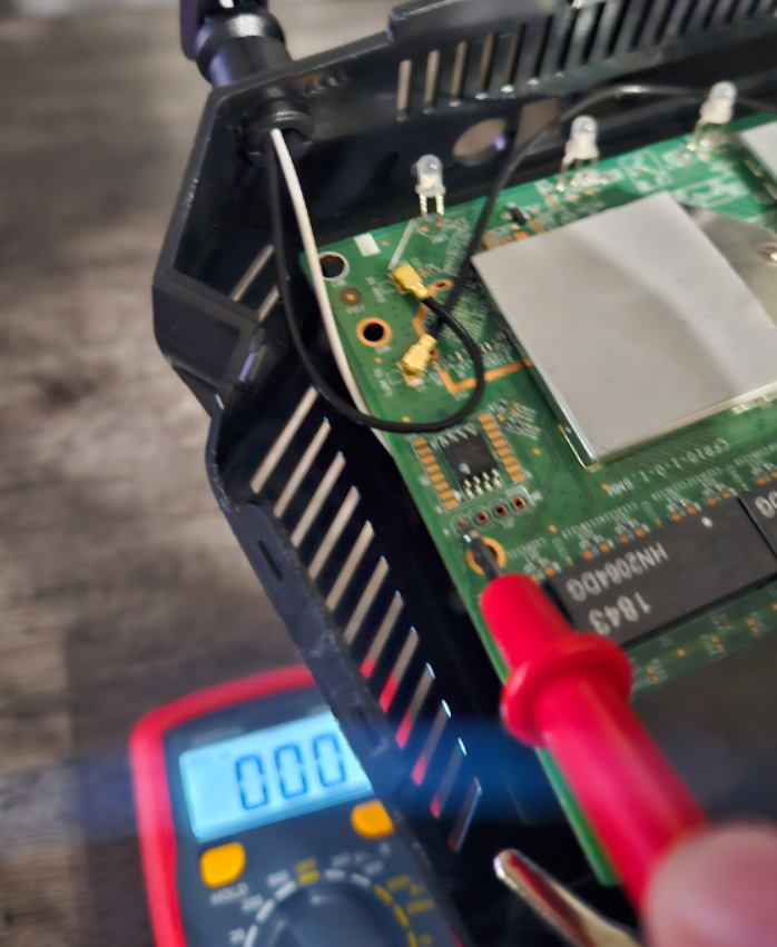
2. Find the RX Pin
The RX pin is the receive line of the UART interface. It accepts incoming data from the connected device. RX is usually easy to identify because it should remain at 0V.
Set your multimeter to 20V DC mode.
With the device powered on, probe each pin while monitoring for a constant value of 0V. On my device, this was the pin marked with an arrow.
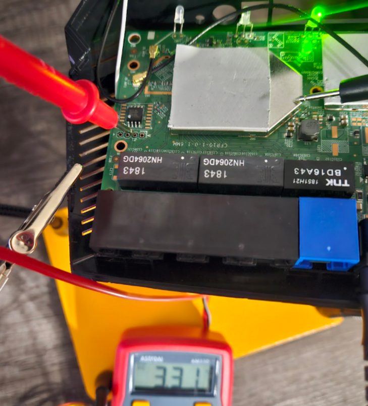
3. Identify the Power Pin (VCC)
The VCC pin should hold a steady 3.3V. This is easy to confirm—on my device, it was labeled JP1.
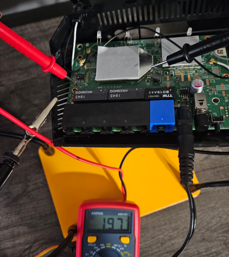
4. Identify the TX Pin
The TX pin is very noisy during startup. To locate it, reboot the device while monitoring each pin’s voltage—the one with the most frequent spikes and dips is TX. On my device, it was the second pin from the left, next to the power cable.
5. Connect the Adapter
Once you’ve identified all pins, map them to the USB-to-UART adapter. Do not connect VCC.
Connections:
- Board RX → Adapter TX
- Board TX → Adapter RX
- Ground → Ground
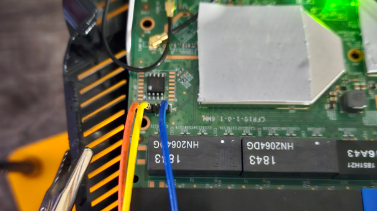
For reference, my wiring was:
- Orange = Ground
- Yellow = Router TX
- Blue = Router RX
Then, on the adapter:
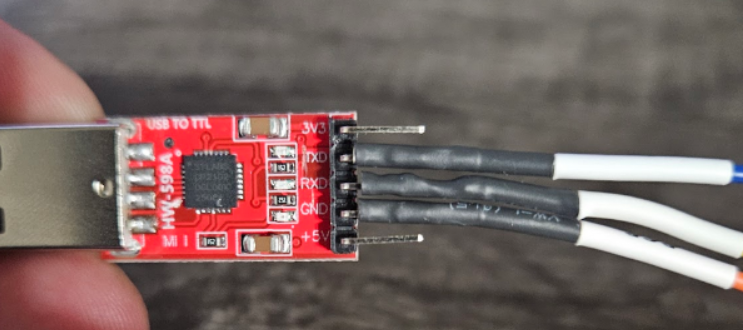
Adapter TX → Router RX
Adapter RX → Router TX
Ground → Ground
6. Open a UART Session
Use the screen utility to start a UART session. If successful, you’ll see the boot log and eventually a root shell prompt.
$ sudo screen -L /dev/ttyUSB0 57600
Now reboot the router and you should start to see a bunch of boot logs…
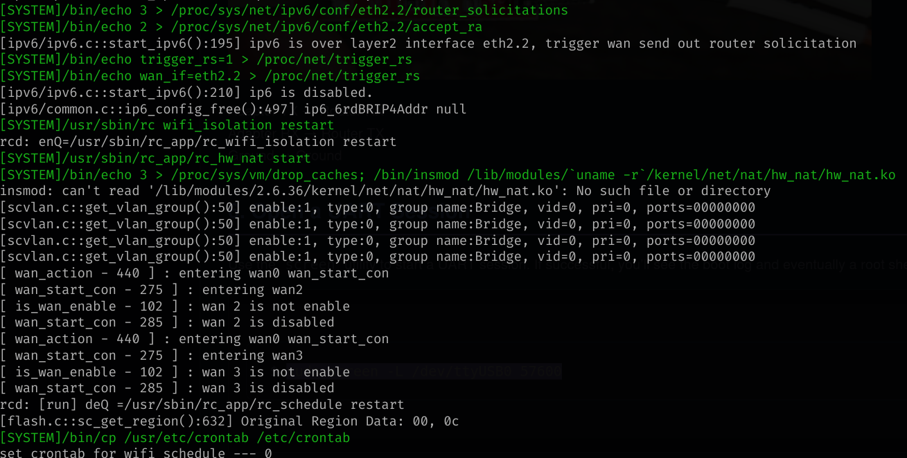
Once the boot sequence is completed we are given a root shell
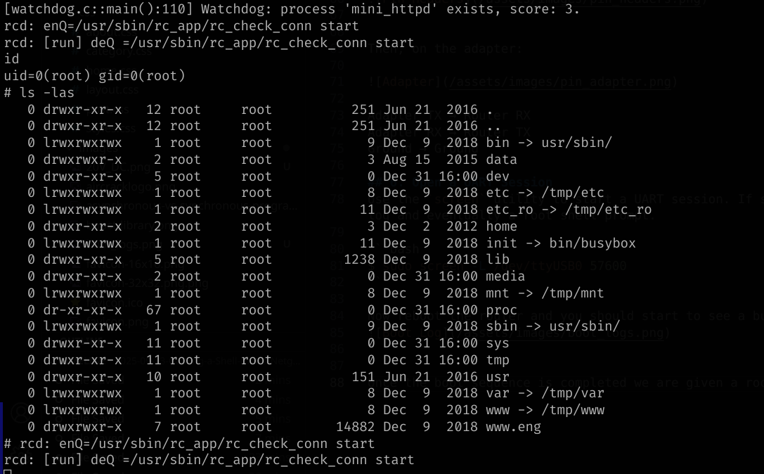
I’m currently focused on enumerating the filesystem and firmware, and I plan to publish blog posts to share my findings.